Output Devices
This week's task was to add an output device to a microcontroller board you've designed and program it to do something.
Introduction
What does Output Device mean?
An output device is any device used to send data from a computer to another device or user. Most computer data output that is meant for humans is in the form of audio or video. Thus, most output devices used by humans are in these categories. Examples include monitors, projectors, speakers, headphones and printers.
Servo motor
A Servo Motor is a small device that has an output shaft. This shaft can be positioned to specific angular positions by sending the servo a coded signal. As long as the coded signal exists on the input line, the servo will maintain the angular position of the shaft. If the coded signal changes, the angular position of the shaft changes. In practice, servos are used in radio-controlled airplanes to position control surfaces like the elevators and rudders. They are also used in radio-controlled cars, puppets, and of course, robots. (Source:https://www.tutorialspoint.com/arduino/arduino_servo_motor.htm)
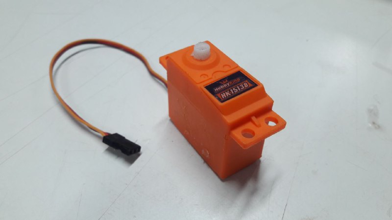
Servos are extremely useful in robotics. The motors are small, have built-in control circuitry, and are extremely powerful for their size.
This week i am trying to understand more about servo motor and also how can this system help me to work my final dynamic facade.
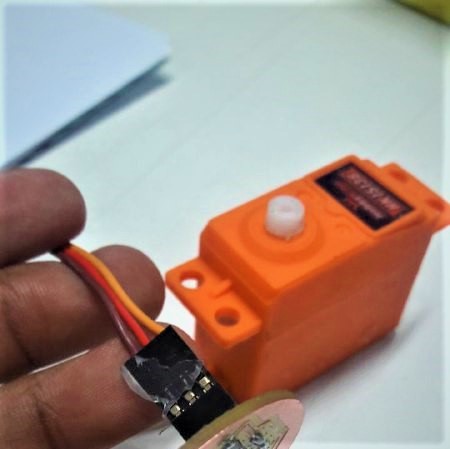
Servo motors have three terminals - power, ground, and signal. The power wire is typically red, and should be connected to the VCC. The ground wire is typically black or brown and should be connected to GND. The signal pin is typically yellow or orange and i have connected the signal pin to Arduino pin number 5,6 since they support PWM (pulse width modulation).This help me to run two servo motor at a time.
Working of a Servo Motor
The servo motor has some control circuits and a potentiometer (a variable resistor, aka pot) connected to the output shaft.
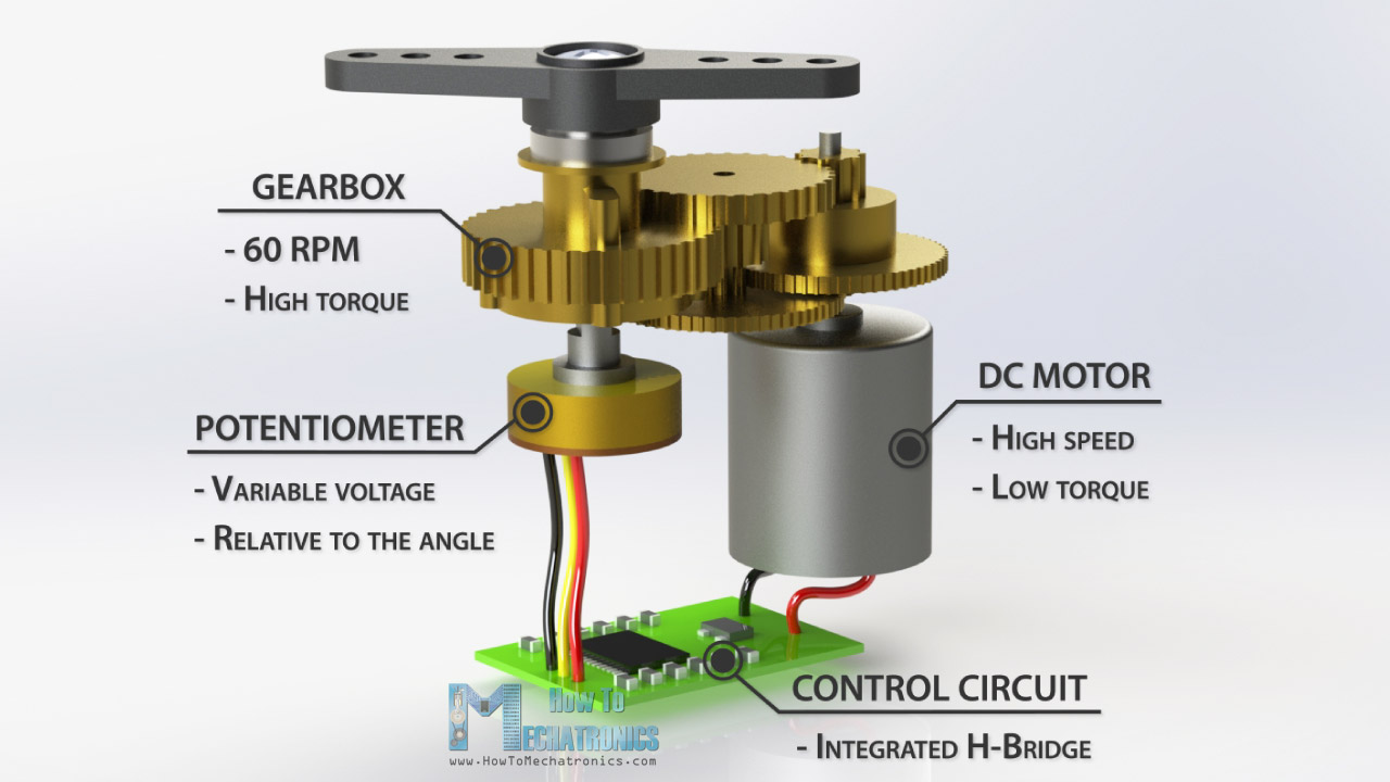
This pot allows the control circuitry to monitor the current angle of the servo motor.The output shaft of the servo is capable of traveling somewhere around 180 degrees. A normal servo is used to control an angular motion of 0 to 180 degrees. It is mechanically not capable of turning any farther due to a mechanical stop built on to the main output gear.
The power applied to the motor is proportional to the distance it needs to travel. So, if the shaft needs to turn a large distance,or if the error value is high the motor will run at full speed. If it needs to turn only a small amount, the motor will run at a slower speed. This is called proportional control.
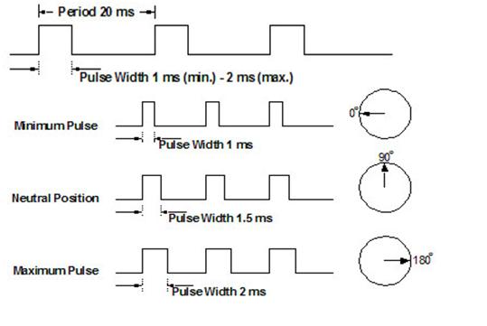
How is the servo controlled?
Servos are controlled by sending an electrical pulse of variable width, or pulse width modulation (PWM), through the control wire. There is a minimum pulse, a maximum pulse, and a repetition rate. A servo motor can usually only turn 90° in either direction for a total of 180° movement. The motor's neutral position is defined as the position where the servo has the same amount of potential rotation in the both the clockwise or counter-clockwise direction. The PWM sent to the motor determines position of the shaft, and based on the duration of the pulse sent via the control wire; the rotor will turn to the desired position. The servo motor expects to see a pulse every 20 milliseconds (ms) and the length of the pulse will determine how far the motor turns. For example, a 1.5ms pulse will make the motor turn to the 90° position. Shorter than 1.5ms moves it in the counter clockwise direction toward the 0° position, and any longer than 1.5ms will turn the servo in a clockwise direction toward the 180° position.
When these servos are commanded to move, they will move to the position and hold that position. If an external force pushes against the servo while the servo is holding a position, the servo will resist from moving out of that position. The maximum amount of force the servo can exert is called the torque rating of the servo. Servos will not hold their position forever though; the position pulse must be repeated to instruct the servo to stay in position.
Circuit Design
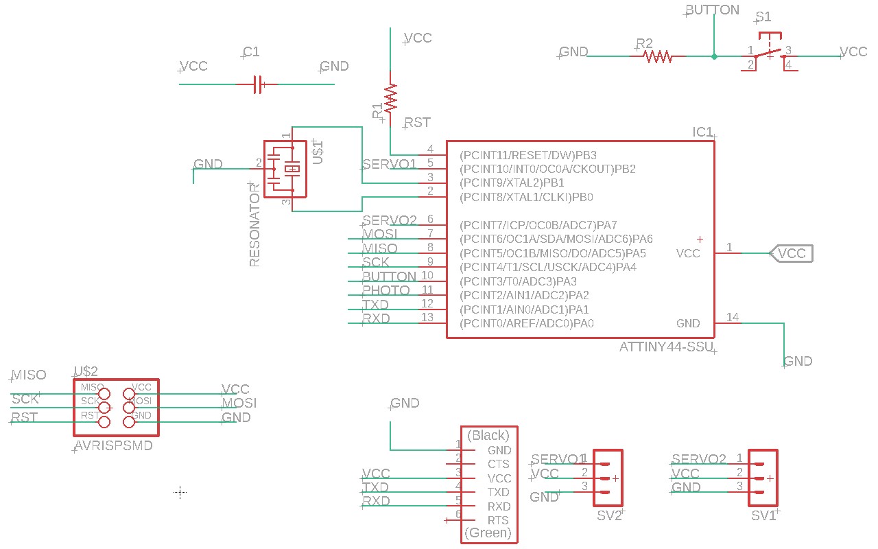
So as I did in previous weeks, I used Eagle software to make the circuit. I used an Attiny44 as micro-controller for the whole circuit.
Now shift to PCB mode and route.I used autoroutting first and then did some manuel routting after that.I added a 0 ohm resistor for completing my circuit board.
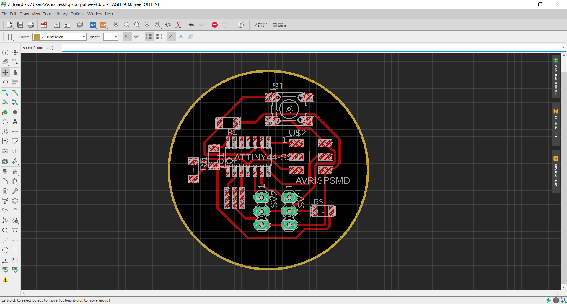
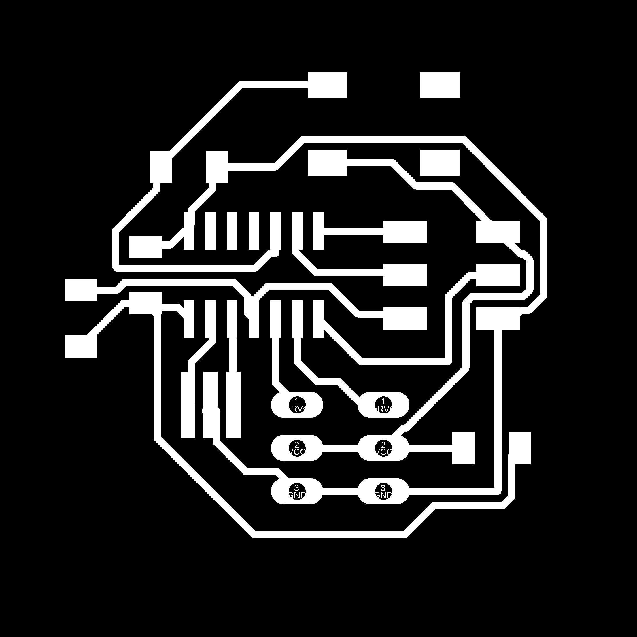
Now "Export" as .png of "Traces", "Drill holes", and "Cut".
Mill trace
Drill Traces

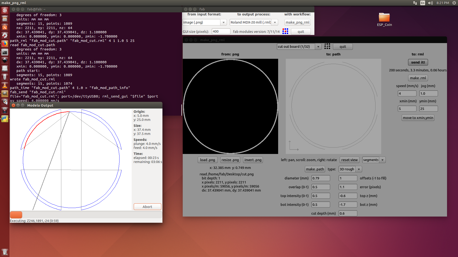
Cut Trace

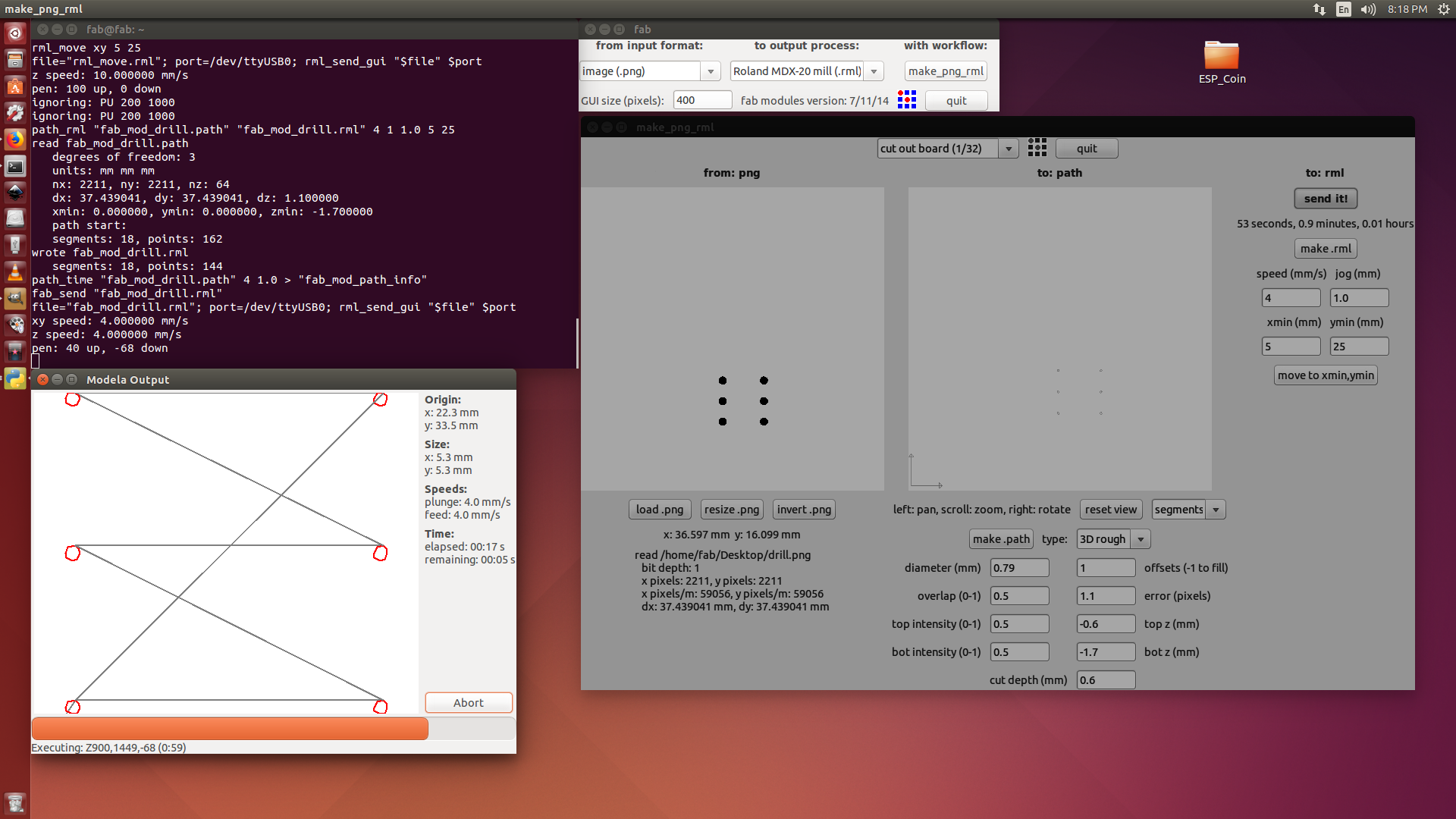
PCB Production
So like I did in the the previous weeks I load the images into fab mods and i used modella to make the PCB
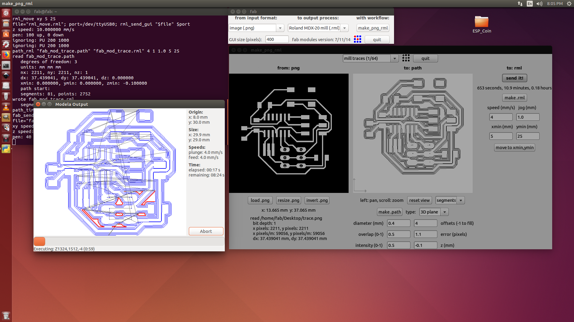
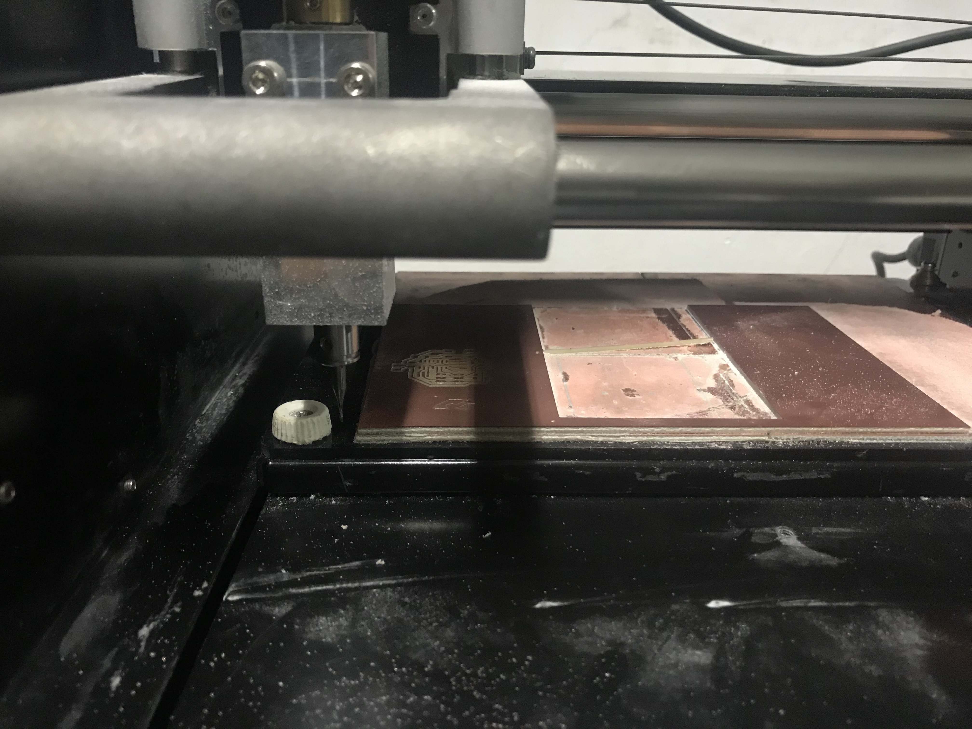
I used a 1/64 inch V-bit for milling the traces
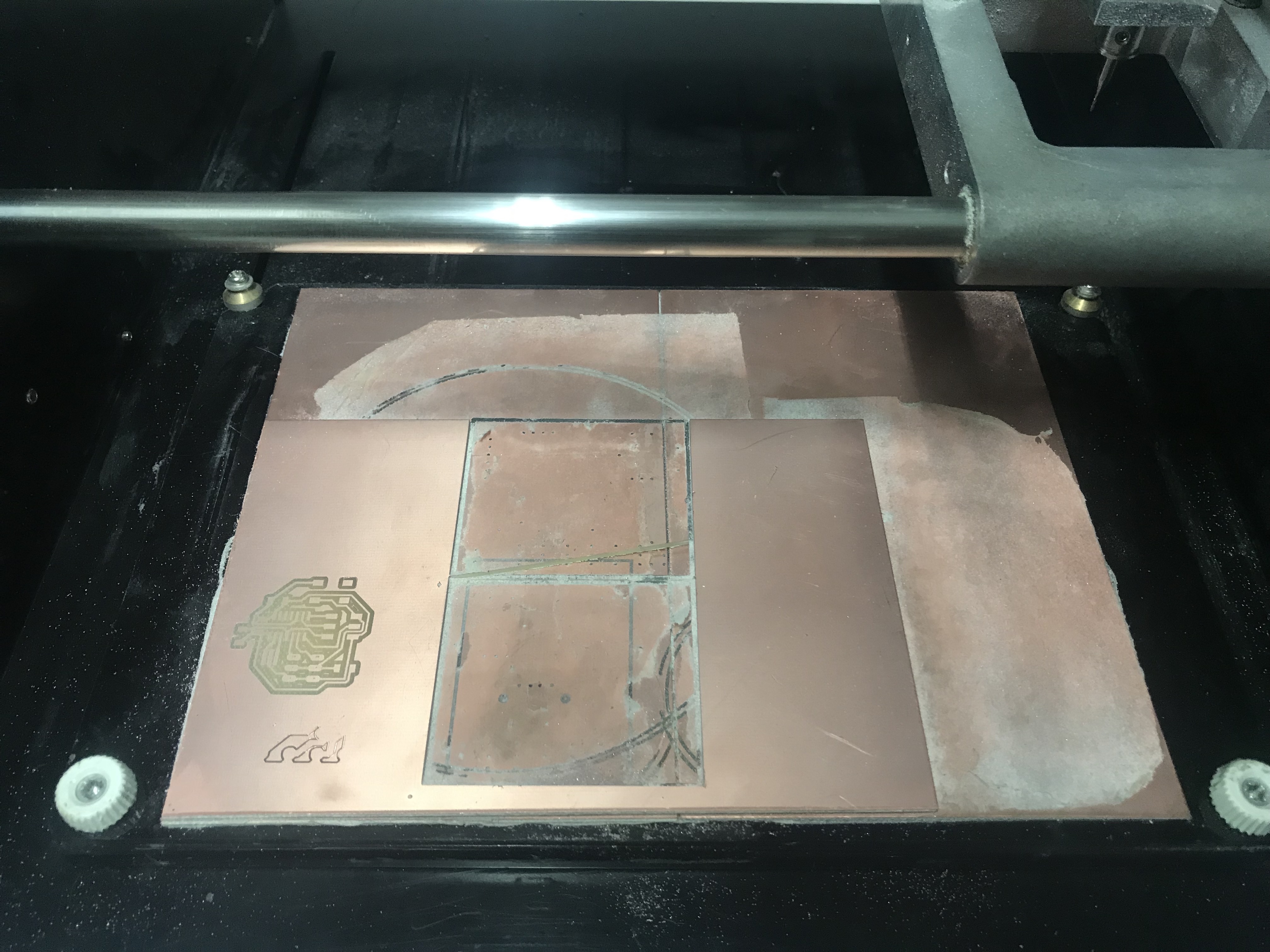
The milling is done and I started drilling the holes for the vias and pads
I have used a 1/32 drilling bit for this operation
After milling i picked the necessary components from the inventory and solder them to the board.
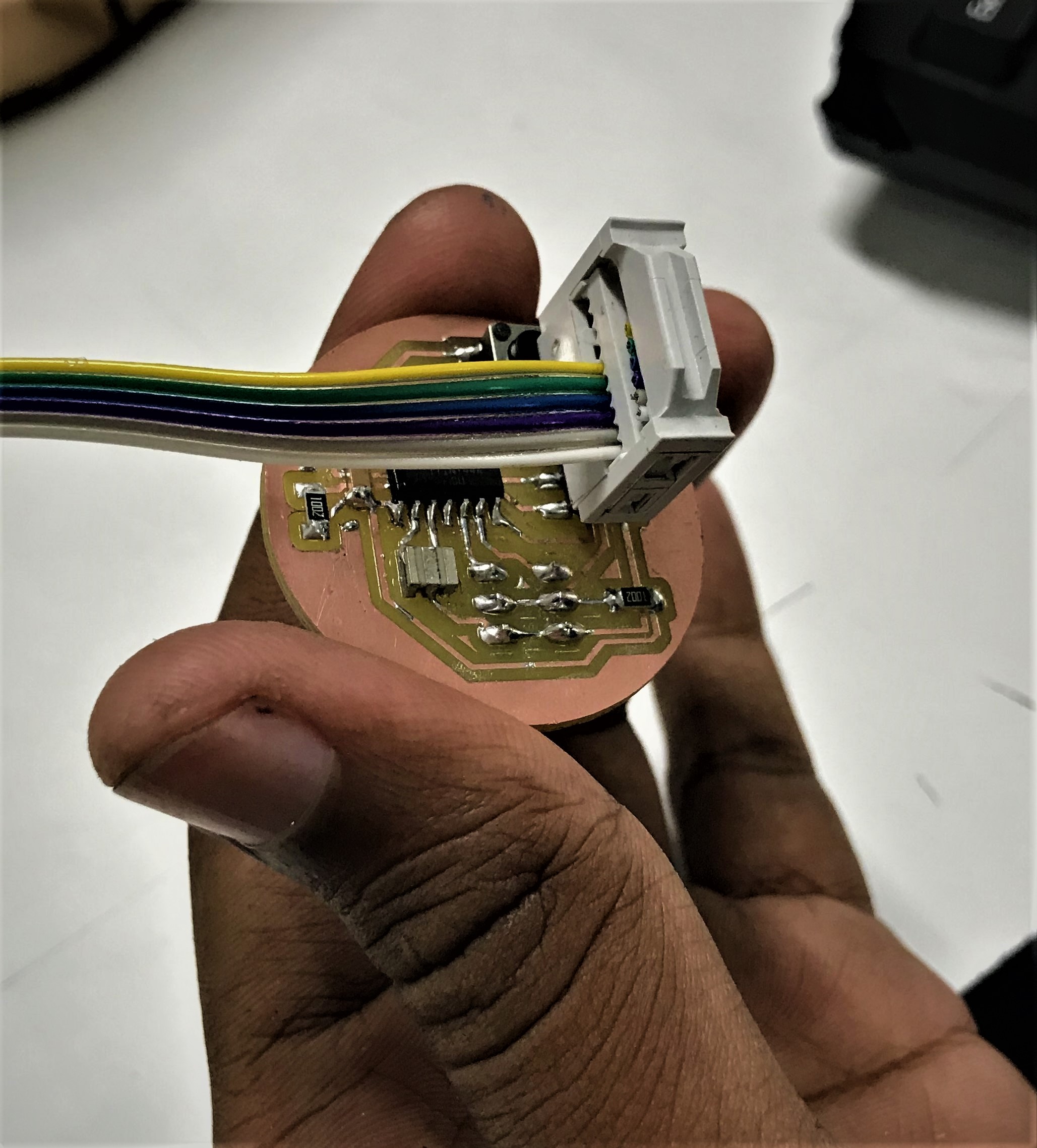
Now I have completed the production process. Now I need to program the board.
You can download the whole project from here.
Arduino programming
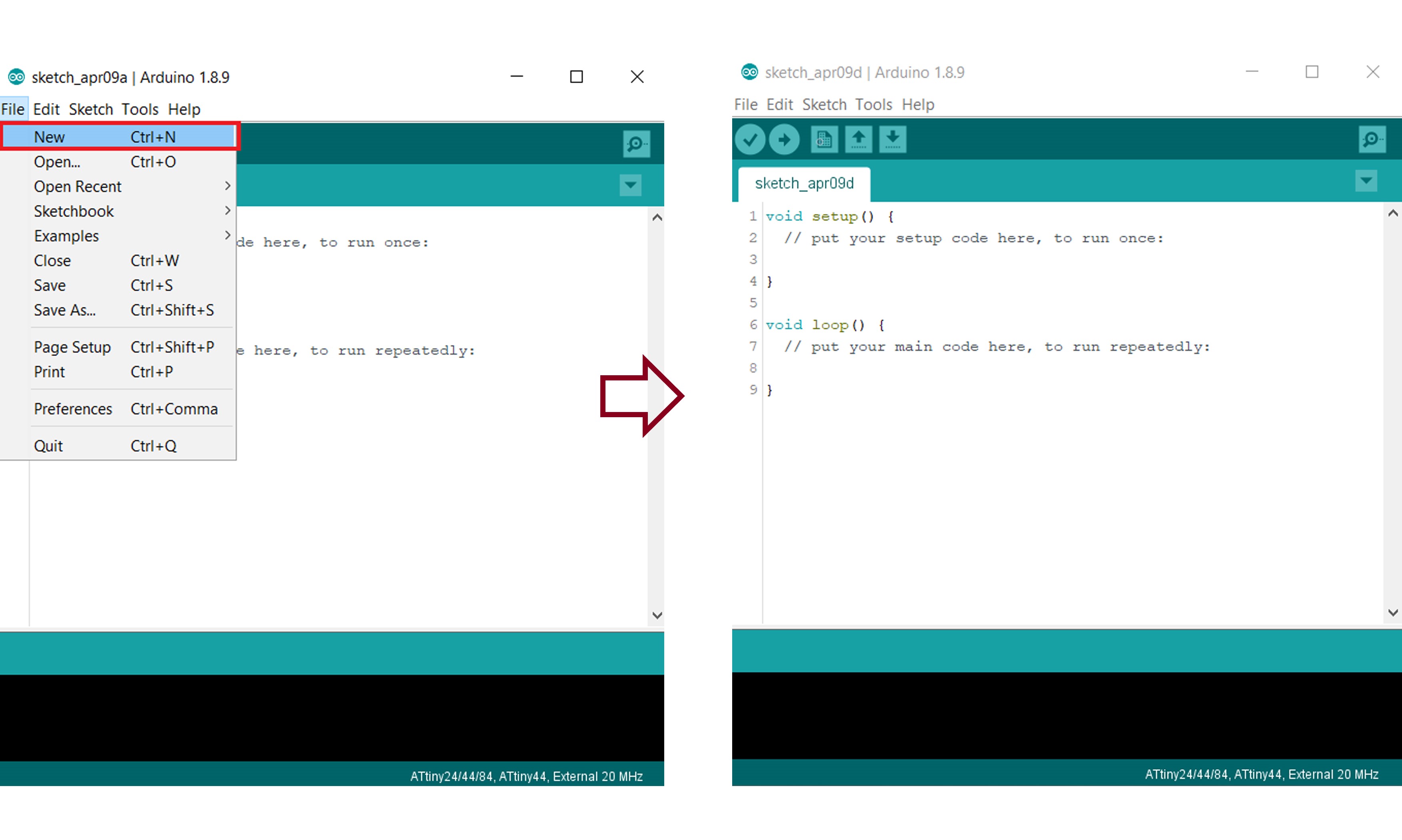
Open the Arduino IDE software on your computer. Coding in the Arduino language will control your circuit. Open a new sketch File by clicking on New.
Arduino code
First i burned Arduino bootloader and after that uploded progarmme using FabISP.First i used Arduino Servo.h library ,i didnt get any output from the servo.I tried to identify the problem but i couldnt.later after going through the old fab academy pages the problem was traced out.Servo didnt woRk because we don't have an 16-bit timer in my servo port. i found Software Servo (SoftwareServo.h).In order to to work with SoftwareServo we need to modify the header file. For this we have to go into the .h and .cpp files and change "WProgram.h" to Arduino.h.
Since i did't used any Voltage Regulator so i can only drive 5v relay.
The Software Servo Library can drive servos on all of your pins simultaneously. The API is patterned after the wiring.org servo library but the code is different. You are not limited to 8 servos, but you must call the SoftwareServo::refresh() method at least once every 50ms or so to keep your servos updating.
(Source:- https://playground.arduino.cc/ComponentLib/Servo)
                        #include <SoftwareServo.h>

                        SoftwareServo servo1;
                        SoftwareServo servo2;

                        void setup()
                        {
                          servo1.attach(7);
                          servo2.attach(8);
                        }

                        void loop() {
                          int pos;
                          for (pos = 0; pos < 90; pos += 1) {
                            servo1.write(pos);
                            servo2.write(pos);
                            delay(10);
                            SoftwareServo::refresh();
                          }
                          for (pos = 90; pos >= 1; pos -= 1) {
                            servo1.write(pos);
                            servo2.write(pos);
                            delay(10);
                            SoftwareServo::refresh();
                          }
                        }
You can download the Arduino code from here.
Demonstration Video
Group Assignments
Measure the power consumption of an output device
Power (W)
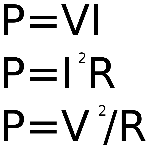
Electric power is the rate, per unit time, at which electrical energy is transferred by an electric circuit. The SI unit of power is the watt (W), one joule per second. For calculating the consumed power, We must know it's
Here is the equation for calculating Power.
Mesuring Power
As you can see in the above equation, we need to find out the variables. For that we need to test for following using a multimeter
Voltage
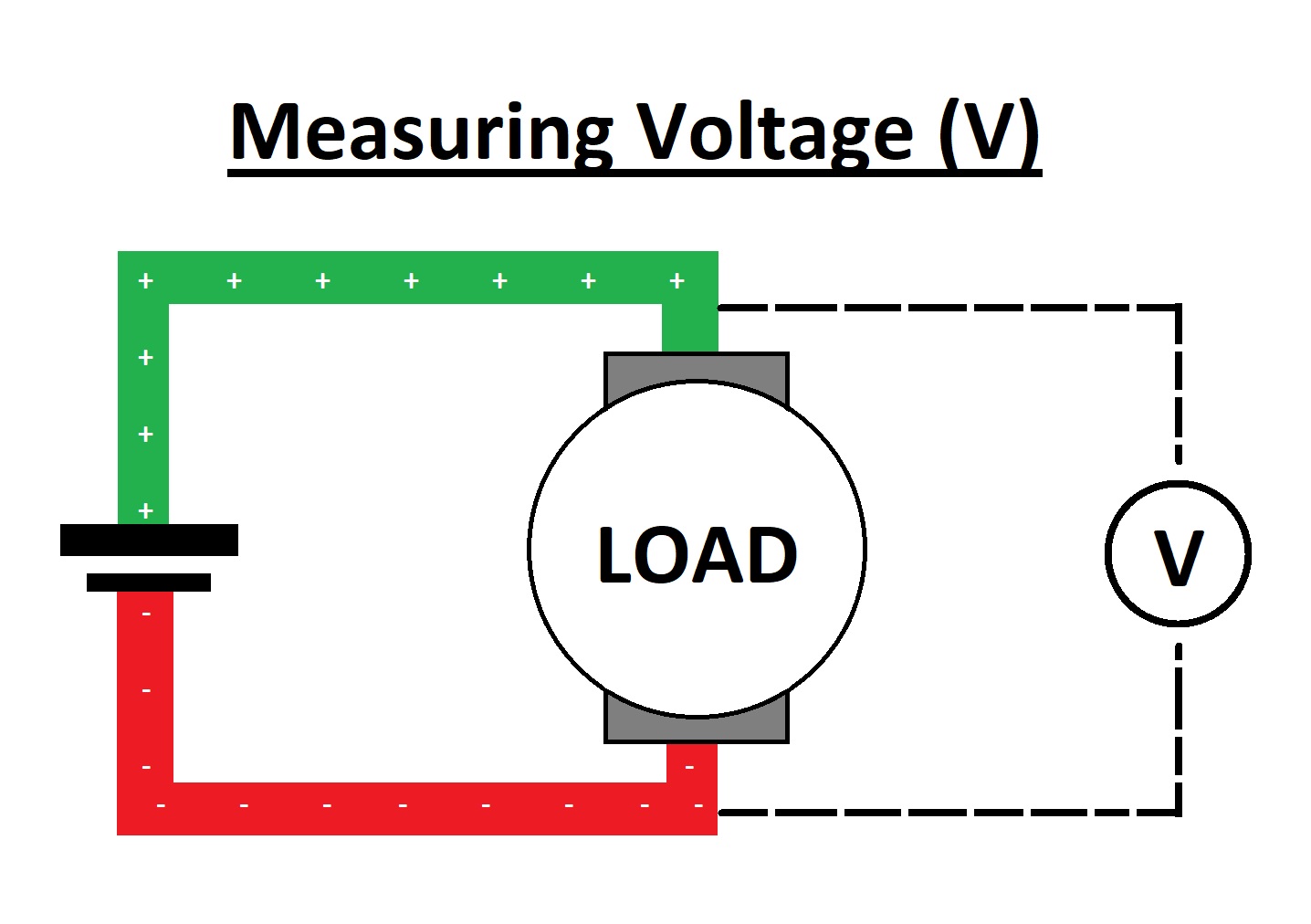
The voltage is calculated by connecting parallel to the "Load". Here Units of Voltage is "Volt(V)"
Current
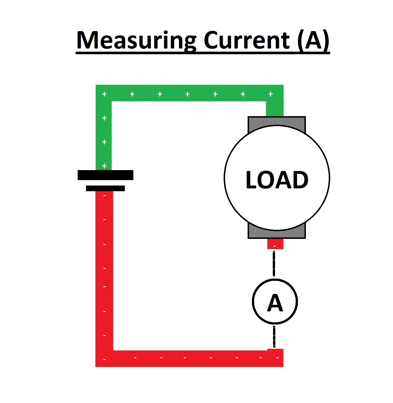
The Current is calculated by connecting series to the "Load".Here Units of Current is "Ampere(A)"
Resistance
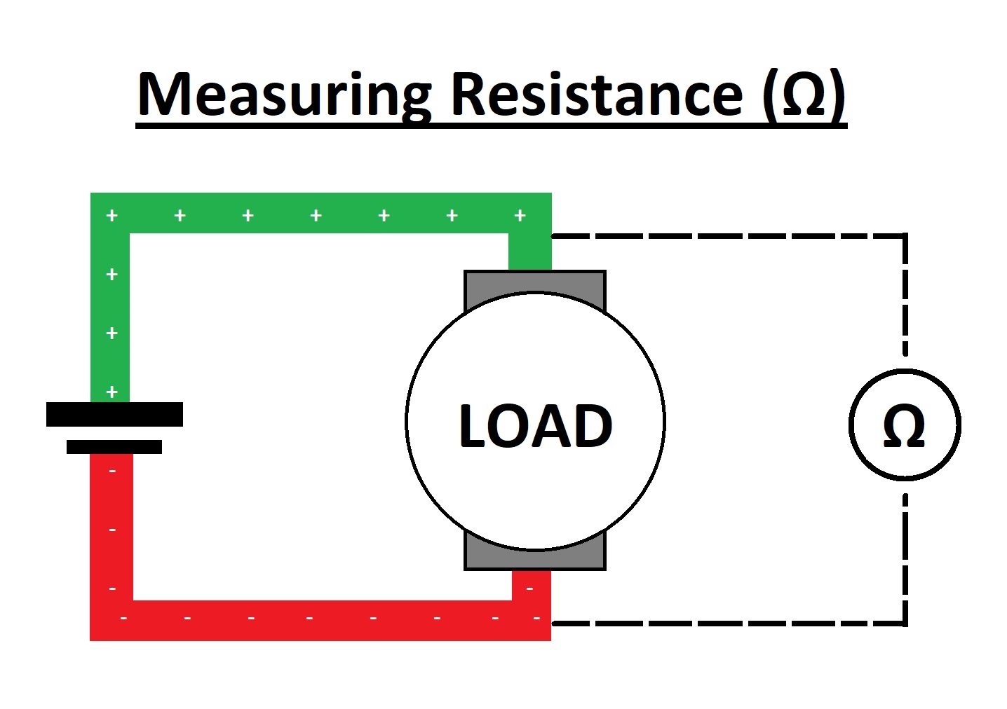
The Resistance is calculated by connecting parallel to the "Load"Here Units of Resistance is "Ohm(Ω)"
So we used a multimeter to find out the variables.
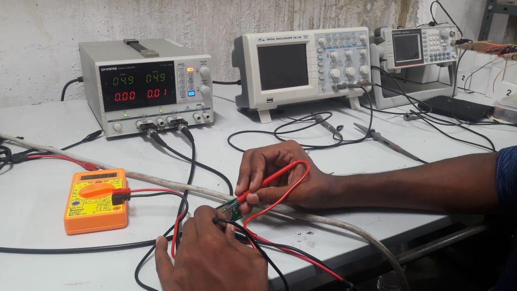
So here we got:
So power can be calculated as:

Substitute values in the equation:
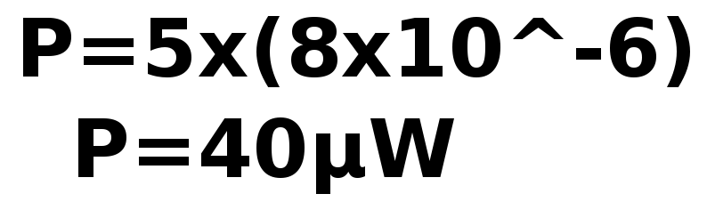
So the power of the output device is "40μW". By repeating the process and we can find other output devices power consumption.